|
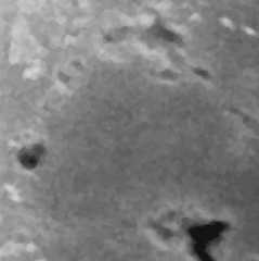
Carbon surface, 2 pA, 0.1 Pa, |
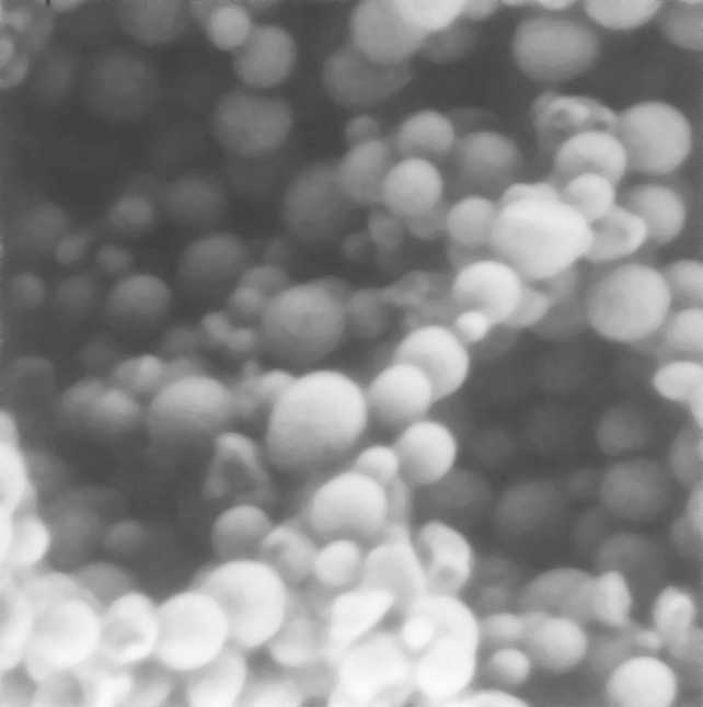
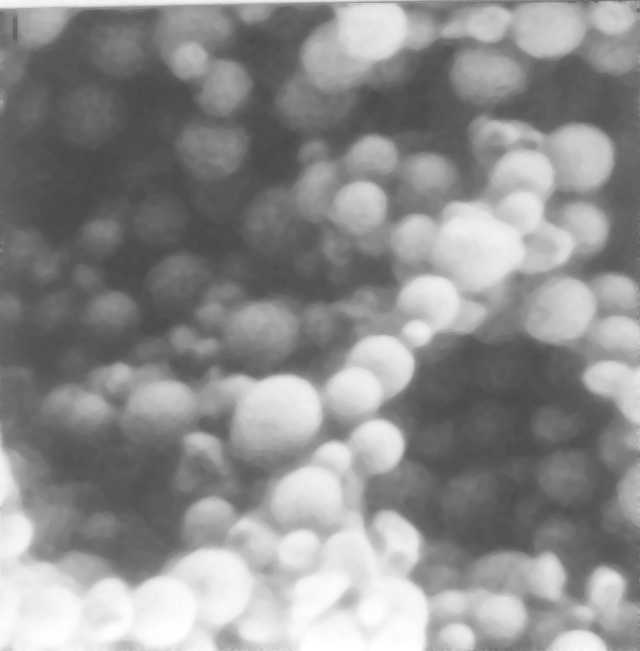
Aluminum oxide spheres, |
|
15 pA, 1100 Pa. |
15 pA, 2060 Pa. |
ESEM Home ||ESEM Research Laboratory||History ||Publications||Patents || Danilatos ||Commercial ESEM||Subject index||Public Images ||contact
The BSE images below were obtained with the minimum possible accelerating voltage available on the prototype ESEM, namely, with 5 keV, and with an extremely low incident beam current as measured in vacuum with a Faraday cage. The beam current and water vapor pressure are given with each image below. All images were made with 1000 scanning lines over 50 seconds
(17), (28). These parameters set a minimum performance to be expected from any properly designed ESEM. A pair of an optimum (calculated) shape of scintillating BSE detectors (17) was used for the images shown herewith, such a a bare carbon surface (very low atomic number material) and aluminum oxide spheres at increasing pressure (with all other parameters remaining constant). The same field of view of the aluminum spheres demonstrates the loss of primary beam and the onset of noise as the pressure increases in accordance with the predictions of theory elsewhere (28). It is this inevitable only loss of beam that should be allowed in the ESEM, whilst any additional or extraneous losses should by all means be avoided. That is the task of every ESEM manufacturer, not yet seen on present day (as of 2007) commercial instruments.|
Carbon surface, 2 pA, 0.1 Pa, |
Aluminum oxide spheres, |
|
15 pA, 1100 Pa. |
15 pA, 2060 Pa. |
ESEM Home ||ESEM Research Laboratory||History ||Publications||Patents || Danilatos ||Commercial ESEM||Subject index||Public Images ||contact