ESEM Science and Technology
Commercial ESEM
Background
In about the second half of 1985, a venture capital
company, ElectroScan Corporation, was formed by a group of
people north of Boston USA, in order to commercialize the idea of
introducing gas in the specimen chamber of a scanning electron microscope
(SEM). The first engineering attempt was based on advice and a patent
by
Alan Nelson (US4720633)
, which however
soon failed to produce any image. By November of 1985, the group sought the
assistance by Danilatos in Sydney who already had produced a working prototype with numerous
publications. Under Danilatos guidance, the first image in a gaseous
environment was obtained at the ElectroScan premises within three
days, i.e. on the 5 February 1986. A
new commercial instrument
, the environmental scanning electron microscope or ESEM was thus born,
and within a few years of manufacturing developments it was to be
fully marketed by 1988.
The first imaging was obtained with the use
of correct differential pumping between two thin-wall apertures
as opposed to the stacking of a series of apertures without pumping between
them as per Nelson patent. The latter stack of apertures traps
air over an extended transition region in which the primary electron beam is
catastrophically scattered and lost. A series of apertures like
that may have a better engineering separation of the vacuum region in the
column from the pressurized specimen chamber than a single aperture of the
same diameter. However, such a series of apertures constitutes the
worst approach for a working ESEM at (a) the lowest beam
kV, (b) minimum beam loss and (c) highest gas pressure.
Initial imaging at ElectroScan was based on the use of a
scintillating backscattered electron (BSE) detector but Danilatos insisted also
on the use and development of a new detection principle already pioneered
and practiced on the prototype since 1983. The latter consisted of
the use of the ionization of gas by various signalsas
a detector for those signals. Since the secondary
electron (SE) imaging constituted the
basic mode of detection in most conventional SEMs, the company work
concentrated on making the gaseous secondary electron detector the basis of
the new instrument, for which a new patent
(US4785182) application was lodged.
ElectroScan also designed and built their own
home grown electron optics column that integrated differential
pumping in the objective lens (US4823006). Unfortunately, whilst
differential pumping was very good, the geometry of a flat bottom pole-piece
placed severe limitations on the integration of detectors and specimen
movement. In this respect, the commercial instrument was severely
constrained from reproducing the results already on record by the
Danilatos prototype. The optimal BSE detectors (17) already developed by Danilatos (see
also design shown here ) could not be used on this
commercial ESEM and thus this mode of detection was compromised. The
first offered scintillating BSE detector, or the later use of third party
BSE detectors of an earlier era have resulted in the commercial ESEM
lagging seriously behind the Sydney prototype ESEM ever since.
It has not been appreciated that both BSE and SE modes of detection
are highly relevant in ESEM developments as opposed to the lopsided development
of one only over the other.
Danilatos ceased to be an adviser to ElectroScan in
1993, whilst ElectroScan was bought by Philips shortly afterwards and by
FEI later on. The introduction of the Philips conical objective lens
was a step in the right direction with much potential, but none of the later
developments were done under any instructions or guidance by
Danilatos. The optimal BSE detectors were not incorporated as they could
and should, whilst new issues emerged as described below.
In recent years Danilatos advised LEO (now Zeiss) on ways
to enter the ESEM market with an ESEM of their own make capable of using the
gaseous secondary electron mode in the extended pressure range, together with
optimal BSE detectors. Success in this direction will be measured by
the extent of such implementations.
Users of commercial ESEMs should be aware that
any deviations of performance from the reported results by the Danilatos
prototype ESEM are the responsibility of the corresponding manufacturer and
that such deviations do not represent any inherent weakness of the principles
involved. Through the entire research period, including the times
when Danilatos received financial support from some companies, all
Danilatos works and reports are based on pure science away from any bias
arising from commercial interests or other considerations. These works
have aimed to establish the theoretical and practical physical limits in the
design and construction of an ESEM. Hence the manufacturers should use
such works as a benchmark and the users should satisfy themselves that
their instruments live up to their expectations.
Problems and Solutions
The commercial availability of ESEM has given a
tremendous impetus in many fields of applications and for the first time the
international scientific community have enjoyed possibilities un-thought of
previously with the vacuum SEM. However, when some commercial design
aspect is not what it should be, it may not be easy to rectify immediately, as
the production of a particular model results in the installation of a
significant number of units in the market. The only or best reaction then
would be for clients provide a feedback somehow to the manufacturer in the hope
that the identified problem will be rectified with the next generation of
microscopes. Some users have expressed certain concerns on instrument
performance and Danilatos occasionally offered some assistance when the users
sought it. Some key problems that need fixing are included herewith:
Electron beam transfer
At the University of Technology (UTS) using a Philips
XL30 ESEM, it was found that imaging became impractical or impossible
as the pressure reached 1000 Pa and acceptable work was mostly
performed with the aid of a cooling stage to lower the saturation water vapor
pressure close to 600 Pa and/or with the use of the highest beam kV. Upon
visual examination of the aperture bullet system, it was thought that the
geometry was in serious deviation from the optimum design and a
computational determination of the gas flow was undertaken. In Fig. 1 the
pressure (or density) gradients are shown along the axis of the bullet
system: A 0.5 mm bottom pressure limiting aperture (PLA1) is
shown on the left side, with the vacuum of the column on the right side
separated by the second (upper) PLA2. Significant gas layers develop
throughout the bullet system between the two apertures, with the highest values
of gas density inside and around the vicinity of the bottom PLA1 which
is also shown at an enlarged view in Fig. 2.
|
.jpg)
Fig. 1 Gas density gradients inside the "bullet" of the
UTS ESEM |
.jpg)
Fig. 2 Gas density gradients (enlarged view) through the pressure
limiting aperture (PLA) of the UTS (previous) "bullet". On the left
side (in red) is the specimen chamber at 10 mbar pressure. The
electron beam has to overcome the stagnating gas inside the PLA cylinder
after already having undergone significant losses in the intermediate
space between the two PLAs. |
|
.jpg)
Fig. 3 Gas density gradients inside the QLD ESEM. There is
less overall stagnating gas than the UTS bullet. |
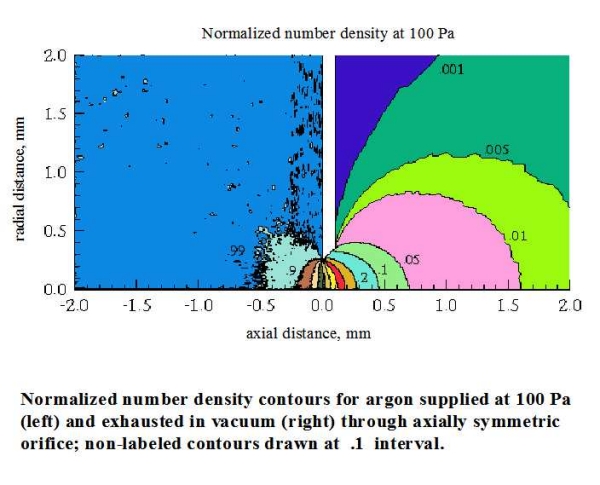
Fig. 4 The pressure gradients with a "thin" PLA are
sharpest and the electron beam losses are
the lowest possible for optimum beam
transfer: See latest paper or (57)
|
The same work was repeated on an early ElectroScan
U3 ESEM model used by the University of Queensland (QLD) and the
corresponding gas density in the bullet is shown in Fig. 3.
Last, the gas flow density was computed for a single thin
aperture having maximum conductance downstream of the flow (free
space). The density contours are shown in Fig. 4. The latter is
taken from a rigorous investigation of the gas flow in the
complete range of pressures up to atmospheric pressure for different gases
including water vapor. In practice, this
situation can be closely achieved with proper care of the aperture construction (e.g. conical
shape) , mounting and configuration, together
with various detectors
.
An integration of the gas density along the axis between
the apertures yields the total mass thickness which the electron beam has to
overcome before it enters the specimen chamber (on the left of PLA1). The
amount of total electron beam loss along the axis in this region has been
computed for a series of conditions and
the results have been
presented in detail twice in (54) and (56) . These results are summarized in
Fig. 5 showing the total electron beam loss for the three cases of
instrument design mentioned above. It is immediately seen that the older
commercial model performs better than the newer, but both perform worse
than the physical limit obtained with a thin aperture, as used on the
prototype ESEM.
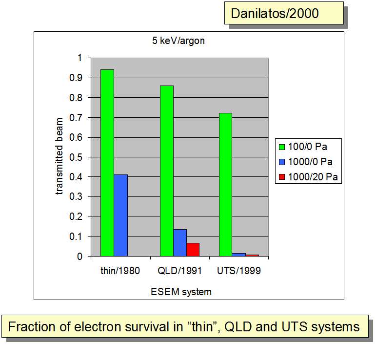
Fig. 5 Comparative presentation of the
electron beam losses for the three cases of PLAs presented in the previous
figures
The results from the work on thin apertures have been
used to establish the electron beam transmission (or loss) in the complete
accelerating voltage range, gas pressure range and working distance range
for different gases. Whilst already published works can lead to these
results, much work still remains unpublished in a comprehensive
form, which however can be available to interested
parties, e.g. manufacturers [See latest paper or (57) ]. By such means we have
established the physical limits which every ESEM should tend to approach, i.e.
the closer to this limit the better. In fact, the Prototype ESEM has been
shown to operate practically at this limit, which has resulted
in the production of the best raw images emanating from the best physics
and not from any image processing technique. One would then expect to have
obtained even better results by modern computer image processing more than 20
years after the pioneering work took place. Unfortunately, this is not
born out by the subsequent commercial instruments like the ones presented
herewith [as it should be stressed again that the later commercial models
perform worse than
the earlier
, and all of them worse than
the original prototype]. Clearly, the thick wall PLA1 (as in Figs. 1,
2 and 3) has a similar effect as the series of apertures used in the
Alan
Nelson (US4720633) patent. It is not clear if this has
been a deliberate engineering attempt to decrease the gas
leak through the thick aperture (at the expense, however, of electron beam
transmittance), or a persistent engineering oversight, or some other
reason. In any case, it seems like
another commercial behavior operating against proven science and
practice, but with some very disappointing results for ESEM.
The consequence of using a cylindrical instead of a thin
wall PLA1 has far more destructive effects in addition to the beam
loss. The cylindrical geometry has a large inside surface which is
prone to quick contamination. Any debris in contact with the surface gets
irradiated and firmly stuck against the surface. At low pressure, or if the user
wishes to revert to vacuum operation, any contamination inside the PLAs will
create serious astigmatism on account of charging. The charging can be so
great by the incident beam that even at increased pressure the gaseous
ionization may not suffice to balance off the amount of charging and hence
imaging becomes problematic and a general malady for the instrument over
all. Furthermore, the position and shape of PLA2 together with the
overall "bullet" (apertures-evacuation assembly) design are critical to prevent
contamination of the upper column, which can drastically reduce the
lifetime of the electron gun and affect normal/efficient electron probe
formation. Users who find it difficult to focus and get clear images
or experience short gun lifetime should become aware of the
causes of their difficulties. Manufacturers should address these problems
both on new instruments and on the ones already in place out on the
market. Solutions do exist for those who wish to have them.
Restoration of the field of view at low
magnifications
Another tested improvement (also solution to
above problems) regards the " field of view" which has been
compromised for a long time in ESEM including the early prototype: The
pair of apertures used creates a "tunnel" vision at low magnifications, which
inhibits, or makes difficult the observation of a large area before the user
zooms-in over a small feature of interest. The practice of increasing the
diameter of PLA1, as a means to increase the field of
view, quickly reduces the working pressure range on account of increased
gas flow and increased gas density gradients in the bullet. As a result,
either very high beam accelerating voltage must be used at low pressure or
imaging is impossible at elevated pressure. This problem has been overcome
with a recent
patent (US6809322) that allows the use
of a much smaller (and thinner) PLA1 with simultaneous much greater
field of view than hitherto used. This at the same
time increases the useful pressure range and decreases the accelerating
voltage needed for the beam. The practical
consequences of such means are enormous: Better resolution on
"soft" specimens with much less beam damage at higher
magnifications/resolutions. Furthermore, smaller PLA (without compromising
the wide field of view) means less probability to contaminate the upper
column, better imaging, long electron gun life, etc...
Accessories, in situ applications and true TV scanning
rate
ElectroScan also developed and sold two
important accessories for the ESEM, namely, a hot stage with which specimens
could be heated at more than 1000 degrees C, and a cooling stage using the
Peltier principle. The hot stage took a big proportion of the R&D
effort, presumably prompted by demand in that area of
application. The cooling stage was mainly prompted by the difficulty
experienced by the engineers to operate the ESEM at room temperature and
high pressure. However, there is also a third ancillary device in
great need, namely, a microinjector device that allows deposition of
liquid droplets of the smallest possible size in a controlled stop/start
manner. A commercial version of such a device became available by the use
of a capillary needle connected to a syringe at ambient pressure outside the
microscope. However, this approach invariably resulted in the
flooding of the specimen stage with water, since the flow could not be stopped
or controlled in any way: By pulling the syringe plug back, the back
pressure at the plug remains at saturation vapor pressure at
ambient temperature, whilst the pressure at the specimen was at saturation
pressure at the cooling stage temperature which was always lower than at room
temperature. If the pressure at the plug is greater than the pressure at
the tip of capillary needle (near the specimen), it is impossible to stop the
flow of water from the syringe to the specimen. Clearly, that approach was
bound to fail, because the water could not be sucked back and could not be
stopped or controlled. Because of this phenomenon, a solution to
the problem was found and published by
Danilatos
and Brancik
(27) a long time earlier: The syringe
was connected to a pipe loop that opens back out to room
(ambient) pressure. Water flowing in the pipe loop supplies on
its way the back of the capillary needle, or water can be freely sucked
back in the syringe emptying the back of the capillary needle. In this
manner, water could be freely pushed back-and-forth between the
syringe and the back of the capillary needle, hence a controlled start-stop
situation could be easily achieved. Such a microinjector was successfully
used for a long time and many hours of video recordings at true TV
scanning rates were obtained during the years 1980-1985. Some still images from those
recordings have been published . Also, some excerpt
recordings were copied to VHS cassettes and retained by
ElectroScan. They were shown at the Albuquerque EMSA Meeting in
1986, as they were also used to promote the ESEM at the outset of its
commercial development. To date, no such video recordings at true TV scanning
rates have ever been shown from any commercial ESEM .
The necessity to use a cooling device on a regular basis
is disappointing, because it is very restrictive as to the ease and range
of applications possible in the commercial ESEM. Having
to control the temperature at a low point prior to observations and
imaging in the ESEM is just another unnecessary complication, even detrimental
to many applications. For example, biological studies of fresh and
living specimens can yield problematic results due to the cooling
device alone. The cooling device should only be used in extreme
situations, whilst for routine operation the ESEM should be usable at room
temperature without further ado.
Backscattered versus secondary electron
imaging
As pointed out before, the use of third party scintillating BSE detectors is most unfortunate, since those have been superseded by
specially designed and devoted ESEM
detectors since 1979. Third party detectors, in general, are
suitable for SEM but not for ESEM, because they cannot fulfill the
stringent requirements of the latter. The manufacturer should have
developed and equipped every commercial ESEM with indigenous (own or homegrown)
design BSE detectors along with the SE gaseous detector. The BSE
certainly should not be offered as an "option" of extraneous detectors of
dubious performance for ESEM. This is an additional reason why
the commercial ESEM has not duplicated, let alone surpassed,
many of the
results obtained by the first laboratory prototype ESEM. There has been
a long and vigorous discussion on the contrast and resolution obtained by BSE
and SE signals and related detectors throughout the 1970s and afterwards.
The best conclusion is that these modes of detection complement rather compete
against each other. Very high resolutions have been demonstrated also with
BSE detectors. Certain misunderstandings have been exploited by
manufacturing expediency in promoting only one mode, as it has happened with the
commercial ESEM. Since patents were owned only on the gaseous SE
detection and not on BSE mode, the manufacturer identified the SE detector
with the ESEM technology in general, and a generation of users have fallen
victim of this misunderstanding too. Good BSE detectors are, in effect,
absent throughout the hitherto existence of commercial ESEM. A
significant percentage of applications would have been far better
implemented in the BSE mode, whilst the lone SE mode has led many users to
erroneous conclusions about the true capability of ESEM. Actually,
the contrast and resolution in ESEM is not limited by either of those modes of
detection in most applications of untreated specimens, but the electron beam
radiation effects often become the limiting factor.
The development of a "helix detector" [also mirrored here]] in a research institute is highly
commendable. Actually, this and scores of other potential developments and
improvements have been envisaged in the "
Theory of the Gaseous
Detection Device " or (36 ) and elsewhere. Many
other research institutes should follow this example. Manufacturers should
also take up specialized developments such as this but not before
the commercial instruments have overcome their existing
fundamental problems and limitations. The "helix" detector certainly does not solve any
of the problems and limitations outlined herewith, and
statements like "However, until the development of the Helix detector, ESEM could not be applied
at the very highest SEM magnifications that are essential for
nanotechnology" are mere misrepresentations of the basic ESEM capabilities in
a proper design. A specialized detector development should not
be given precedence over eliminating other existing basic flaws, the cart
should not be placed before the horse and ESEM should not be
downgraded to operating only at low vacuum. The manufacturers need better direction on
the grounds of a comprehensive understanding of ESEM instead of pursuing
haphazardly a few developments here and there. This brings
us to face the cause of many problems closely: The
self-portrayed "road mappers (on page
10)" of ESEM have not yet
produced a machine to its full potential. More work is needed
to extricate right from wrong.
The basic gaseous
detection device followed by the many modifications as described in
the
Theory of the Gaseous
Detection Device can serve the ESEM for many generations of commercial models to
come, whilst we are not short of novel
detection ideas if the manufacurers were willing to expand even
more.
Resolution of ESEM, radiation effects and instrument
sensitivity
It has been shown that the resolving power of
an ESEM is determined by the electron probe diameter in the same manner as
with a SEM.
Test specimens of gold particles on
carbon can be equally resolved by both instruments
.
Manufacturers compete in the "battle to resolve the Angstrom" and the "nano-"
has become the latest catchword to impress the world with various
"nano-technologies". However, the physics of electron beam-specimen
interactions has not changed an iota no matter how smart an instrument
claims to be. The actual resolution may be spoiled in most applications by
the very radiation effects that accompany the highest magnification
available. For example, if we look at
Figs. 100 and 101 of
Foundations... the edge definition of an ordinary specimen at
moderate magnifications appears blurred following irradiation. The
unaware user would in vain try to sharpen the focus in this case, or may
think the instrument is faulty. This and other types
of irradiation effects have been reported not only with ESEM but also with
SEM. However, ESEM is more demanding in this area because it claims the
privilege to look at natural specimens. Apparently, blasting of a
wetting specimen by the electron beam should not usually be the case
of study (e.g. see "Video Tour EVO® Tour 4 of 5" on coffee grain, which is also directly
mirrored here). When one often or easily
sees "bubbling" on the image, one can suspect that either
the instrument or the operator is not performing well (i.e.
optimally). Specimens should be kept as unspoiled as possible. The
only way to achieve this is by the use of the absolute minimum
radiation dosage at the maximum magnification. Actually, a glance in
various journals immediately reveals that the vast majority of applications have not been done or have not
demanded the use of the ultimate resolving power of the instrument in
use. Therefore, it is imperative that the "sensitivity" of microscopes
rather is of prime consideration and should not be compromised
or overlooked by the manufacturers in their
planning to improve their instruments. An optimum beam
transfer [see latest paper
or (57 )] together with the supply
of the most sensitive detectors requiring minimum electron beam intensity
and accelerating voltage are the prime factors that have brought
radiation
effects under control at the minimum possible physical
limit. This is an aspect of paramount importance in the practice of this
technology, an aspect not to be overlooked at all times.
Specimen transfer and environmental
control
Another flaw that has plagued the commercial
instruments is the problematic control of relative humidity, of wetting and
drying a specimen in a controlled way. There are a number of publications
from the use of commercial instruments that bear evidence of this limitation, of
which every user must be aware. This has been caused by the lack of a
specimen exchange chamber (airlock). The entire specimen chamber of
commercial ESEM is evacuated each time a specimen is changed and it
is practically impossible to remove the ambient
gas without initially lowering the relative humidity well below the
100% level. Some users have devised a routine of cycling the pumping a
number of times before they can reach a saturation (wet) state in the
chamber, but this imposes severe limitations on many applications,
especially in the examination of fresh and live biological samples
where relative humidity matters. This is time consuming and detrimental
both to the application and to the instrument in which huge pressure
differentials on the PLA (and gas flow) increases the chances of
contamination. The prototype ESEM has overcome these limitations right
from the outset because the modified JEOL JSM-2 SEM is equipped with
an airlock, which is appropriately connected to the pumping system of the
ESEM (see OPERATION AND APPLICATIONS as well as other
numerous publications by Danilatos). Specimens are inserted in the
specimen chamber within a minute and never have to undergo any drying condition
whatsoever. The airlock contains a quantity of water which allows
lowering of the ambient pressure monotonically to the 100% (wet) condition, and
then the specimen is inserted in the main chamber which is continuously
maintained at 100% relative humidity without interruption with each specimen
change. This is speedy and safe both for the specimen and the overall
operation of the instrument, as is outlined in relevant publications ( 28 ). Incorporation of a water
reservoir inside the commercial chamber would again limit the scope of
applications and relative humidity control, hence the inclusion of an airlock
properly integrated with the pumping manifold is the best solution to an
existing market problem. Perhaps manufacturing expediency, once more,
determined the elimination of a classical airlock from routine instruments as
those instruments were addressing the needs of the bigger industrial market
applications (presumably) than lesser market of biological
applications. The validity of such an argument may be questioned, as it
may also be questioned why an instrument has to have only one or the other
specimen transfer mechanism and not both. The whole problem is reduced to
a problem of engineering efficacy. It is finally reduced to a question of
whether the engineering management is in tune with and qualified to address
these problems.
Conclusion
It is disappointing that good workers, while they
genuinely strive to understand the new physics of ESEM, accept their
commercial instruments uncritically. Indeed, it is strange that some
users, especially of latest commercial ESEM, seem oblivious to the
severe limitations of their instruments and have actually become
subservient to them (after all, they have to justify their budget
expenditure). They wouldn't even think of modifying their instrument or risk losing
their warranty (after all, their assumption is that they got the "latest"
technology in the field!). Thus, a whole generation of well intentioned workers
is trapped. This may explain why we often come across some
pompous paper titles hinting at thorough and deep-going scientific work, whilst
the authors cannot even untangle themselves from the artificial constraints of their
machines. None of these works has improved the commercial ESEM one iota,
even in full view of the latter being downgraded to low vacuum SEM.
Pompous titles yes, but real progress none. It now requires some
courageous individuals to get out of this trap, scientists should
start speaking out, at least some of those still operating the older models that
provide better outcomes. The rest of the truth must be sought elsewhere when we
examine events behind the academic
world .
Based on the evidence given above, one should appreciate
why there are several commercial ESEMs around that represent a serious
deviation from the goals and achievements originally obtained and
set. With any description of "how ESEM works" [also mirrored here ], it must be
made clear that the description applies to a particular commercial ESEM type and
not to ESEM in general. The instructions may well be based on
a retrogressive design: That is an example of the artificial
limitations imposed on working pressure range, beam kV, field of view, image
noise (hence dependence on image averaging), working distance, temperature
(hence dependence on cooling), charging of large insulating specimens,
etc. The ESEM, in general, is not like SEM with "two added degrees of
difficulty" but a particular commercial
brand may be so. It is ironic that the truth (fortunately) is exactly in the opposite
direction: ESEM has created new degrees of freedom and ease of operation!
A more general description of how ESEM works can be found here .
A proper ESEM is the one that allows the user to operate
at room temperature, under fully wet conditions, at low kV (less than 5 kV),
with sufficient space to allow most applications and ancillary devices
(like a microinjector), and a large field of view. These, in
turn, allow excellent contrast and resolution with minimum or no
specimen damage, all of which, in turn, allow an unlimited number of
applications. However, ill-conceived commercial instruments may only have
an opposite effect on the market, which, in turn, is used as internal company
argument against normal progress. The ESEM, in general, should not be
identified with any single form of commercial make. The term ESEM was
introduced prior and independently of the commercial developments and there
should be a clear distinction of terminology regarding the technology per se and
various commercial forms of ESEM.
It is very striking if one considers the achievements at the very
outset or ( 1 ) of this work, let alone the
breakthroughs that followed in the decade after that. When imaging could
be obtained at pressures in excess of 50 mbar (5000 Pa) in the
year 1978 with the simplest modifications to a 1968-make of an old SEM
and with meagre resources and a shoestring budget, whilst present day
"state of the art" machines are constrained to low vacuum and pressure with
crude operational parameters, the scientific community becomes seriously
concerned. This exposition clearly shows that beyond the general
understanding of the foundations and principles involved, success
also involves the art of adequate precision in the design and construction
of an ESEM. This clearly indicates that the engineering crudeness factor of various design parameters on commercial instruments is at least
one order of magnitude out of the scientifically prescribed one. Any
scientist or user of this technology must wonder why this is so. Three
broad causes can be proposed: (a) The commercial engineers have never
experienced the levels of achievement by the
ESEM Research Laboratory , (b)
they may have not read or have never understood the
published works , (c)
there are other obscure reasons outside scientific logic.
Clearly, an ESEM optimally designed to operate at high
pressure is automatically superior in performance at low pressure or low vacuum
without further ado: An optimal ESEM design is good both for low and high
pressure work. The internal argument used by manufacturing personnel that
"there is not high demand for high pressure work" is very poor indeed:
Firstly, it is absolutely false to claim that there is not high demand in the
market for high pressure work. Secondly, even if the previous claim were
to be correct in some way, you do not go about compromising and corrupting the
engineering design because allegedly there is no high demand in the high
pressure range. This is ludicrous and obscure thinking (yet
it happens!). How can you expect a demand for high pressure work if
the current offerings to an unaware market are ineffective? Furthermore,
you simply cannot expect the market forces alone to ensure optimum operation of
the ESEM product, since this is not an every day commodity like milk and
bread, or cars. The market forces to operate for this commodity
(ESEM) can have a time lag of 20-30 years and have no immediate
practical consequence. The first commercial ESEM did not come
about because customers were demanding it from the manufacturers. It was
the initiative of a small group of people who promoted it in the first place and
the market followed. After that, supply and demand go hand in hand but the
key is to maintain a healthy supply. A good product will increase
demand. Bad reputation will stifle the market. Hence the
manufacturers are obliged to live up to the expectations of this newly
created market, if progress is to made and if they are genuine in their
commitment to serve science and technology. In parallel, scientists must
press ahead with progress despite all odds.
Herewith, we have exposed several instances
of artificial technological mishaps, unnecessary and avoidable
throughout ESEM's commercial existence. We can also understand why an
ESEM should not simply be identified with the commercial detector of "GSED"
(a misnomer for the gaseous detection device) as is often inappropriately
done. For what is the use of the latter detector in an machine that
results in massive electron beam losses during transfer, or incurs frequent
contamination and image deterioration, or sustains only short electron gun life,
or desiccates and kills fresh specimens prior to achieving 100% relative
humidity, or blasts delicate specimens under forced high accelerating voltage
beam operation, or has to operate only with a cooling device mainly
at freezing conditions, or provides poor BSE imaging, or is cumbersome
to operate, or has long down times and requires frequent service
requests? ESEM is the synergy of a host of technological musts. In
short, we have demonstrated several clear cases for
improvements waiting for implementation for a long time
now. There is no technological justification of why these problems have
appeared at all. The explanation must be sought in the management of human
resources by the manufacturing world and in the tolerance or
misguidance demonstrated by the academic world . The historical reasons for the delay in
the implementation of what otherwise should have been plain and natural
ESEM development during the last 20 years constitutes a topic to be dealt with
separately, when we look behind
the commercial world.
All obstacles above have a solution and so scientists and
users of ESEM should not lose heart in their continued efforts to do the
best out of this unique technology even in the present form available
to them, whilst striving to steer the commercial ESEM in the right
direction. Manufacturers must realize that there is a technological
"vacuum" in the market which should be filled with a fully fledged ESEM in
accordance with proven specifications (e.g. optimum design
specifications ), which still remain beyond the reach of mainstream
users. Bygone previous patent limitations, the key now is the
"know-how" for ESEM excellence. It remains to be seen which
manufacturer will be the first to fill this vacuum...
Please note: If your experiences relate to any of the
problems outlined above, you may wish to send a comment to
esem@bigpond.com